112 Results
View results:
Sort by:

The ASCE 7-22 Standard [1], Sect. 12.9.1.6 specifies when P-delta effects should be considered when running a modal response spectrum analysis for seismic design. In the NBC 2020 [2], Sent. 4.1.8.3.8.c gives only a short requirement that sway effects due to the interaction of gravity loads with the deformed structure should be considered. Therefore, there may be situations where second-order effects, also known as P-delta, must be considered when carrying out a seismic analysis.

The data exchange between RFEM 6 and Allplan can be done using various file formats. This article describes the data exchange of a determined surface reinforcement using the ASF interface. This allows you to display the RFEM reinforcement values as level curves or colored reinforcement images in Allplan.

The fatigue design according to EN 1992-1-1 must be performed for the structural components subjected to large stress ranges and/or many load changes. In this case, the design checks for the concrete and the reinforcement are performed separately. There are two alternative design methods available.

To evaluate whether it is also necessary to consider the second-order analysis in a dynamic calculation, the sensitivity coefficient of interstory drift θ is provided in EN 1998‑1, Sections 2.2.2 and 4.4.2.2. It can be calculated and analyzed using RFEM 6 and RSTAB 9.
The coefficient θ is calculated as follows:$$\mathrm\theta\;=\;\frac{\displaystyle{\mathrm P}_\mathrm{tot}\;\cdot\;{\mathrm d}_\mathrm r}{{\mathrm V}_\mathrm{tot}\;\cdot\;\mathrm h}\;$$
The coefficient θ is calculated as follows:$$\mathrm\theta\;=\;\frac{\displaystyle{\mathrm P}_\mathrm{tot}\;\cdot\;{\mathrm d}_\mathrm r}{{\mathrm V}_\mathrm{tot}\;\cdot\;\mathrm h}\;$$

For the ultimate limit state design, EN 1998‑1, Sections 2.2.2 and 4.4.2.2 require a calculation considering the second‑order theory (P‑Δ effect). This effect may be neglected only if the interstory drift sensitivity coefficient θ is less than 0.1.
![Spans Based on Figure 5.2 from [1]](/en/webimage/039540/3493372/01_Abmessungen_EN.png?mw=640&hash=a3c436931baff3514db261b2d11bfa39abae9170)
In order to correctly design a downstand beam or a T-beam in RFEM 6 using the Concrete Design add-on, it is essential to determine the flange widths for the rib members. This article describes the input options for a two-span beam and the calculation of the flange dimensions according to EN 1992-1-1.

In order to be able to carry out a pushover analysis, it is necessary to transform the determined capacity curve into a simplified form. The N2 method is described in Eurocode EN 1998. This article should help to explain what a bilinearization according to the N2 method involves.

For the stability verification of members using the equivalent member method, it is necessary to define effective or lateral-torsional buckling lengths in order to determine a critical load for stability failure. In this article an RFEM 6-specific function is presented, by which you can assign an eccentricity to the nodal supports and thus influence the determination of the critical bending moment considered in the stability analysis.

The goal of using the RFEM 6 and Blender with the Bullet Constraints Builder add-on is to obtain a graphical representation of the collapse of a model based on real data of physical properties. RFEM 6 serves as the source of geometry and data for the simulation. This is another example of why it is important to maintain our programs as so-called BIM Open, in order to achieve collaboration across software domains.

Consideration of p-δ Second-Order Effects in RFEM 6 and RSTAB 9

This technical article presents some basics for using the Torsional Warping add-on (7 DOF). It is fully integrated into the main program and allows you to consider the cross-section warping when calculating member elements. In combination with the Stability Analysis and Steel Design add-ons, it is possible to perform the lateral-torsional buckling design with internal forces according to the second-order analysis, taking imperfections into account.

In order to create a surface model with failing supports close to reality, an option called "Failure if contact perpendicular to surfaces failed" is available in RFEM 5 for contact solids under "Contact Parallel to Surfaces".
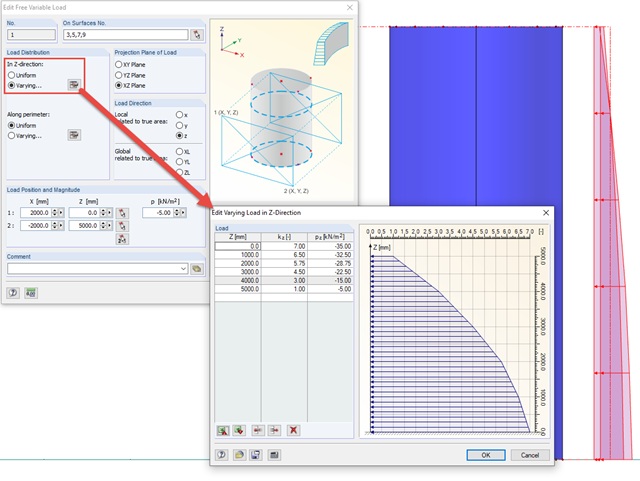
In order to apply loads that are variable in height and perimeter to rotationally symmetric objects, RFEM provides the free variable load.

RFEM and RSTAB can calculate the critical load factor for each load case (LC) and each load combination (CO) in the case of a geometrically nonlinear calculation (second-order analysis and following).
If you want to only change a few geometry parameters in a model, it is not always necessary to remove these structural parts and redefine them.

RF-CONCRETE Members also includes the design of a shear joint. In order to perform this design, you should select the "Shear joint available" check box in Window 1.6, Shear Joint tab.

In RFEM, you can display the contact properties between two surfaces by means of contact solids. Among other things, you should ensure that both contact surfaces of a contact solid have the same integrated objects. Therefore, when modeling the contact surfaces, we recommend using the copy function in order to create the second contact surface.

You can make various settings in order to achieve a clearly‑arranged display of the result values. For example, some users may not want the white background in text bubbles. You can adjust the background in "Display Properties" using the Transparent and Background color option.

Inserting holes in surfaces is very easy due to the large selection of tools. In order to insert holes or drilling in solids, it is necessary to keep in mind that an opening at the beginning and the end of a continuous hole must be created, as well as a surface that separates the hole from the solids.

In the age of BIM, data exchange between the various disciplines of structural engineering is becoming increasingly important. Since each software has its own specifications with regard to the description of cross-sections and materials, RFEM and RSTAB offer a conversion table (mapping file).

Very small torsional moments in the members to be designed often prevent certain design formats. In order to neglect them and still perform the designs, you can define a limit value in RF‑/STEEL EC3 from which torsional shear stresses are taken into account.

RFEM and RSTAB offer many display options in the Display Navigator. They can be completely different, depending on their function. You often have to click several times to make certain changes. If you want to optimize your work, you can create user‑defined views. In these views, you can save all specified settings. The following example illustrates this principle.

In order to detect the governing internal forces of a plate, a checkerboard loading is commonly used. Since it is not necessary to divide the surface into individual load segments, loading is usually carried out by means of free rectangular loads. In the case of many loads, the normal load display can become somewhat confusing.
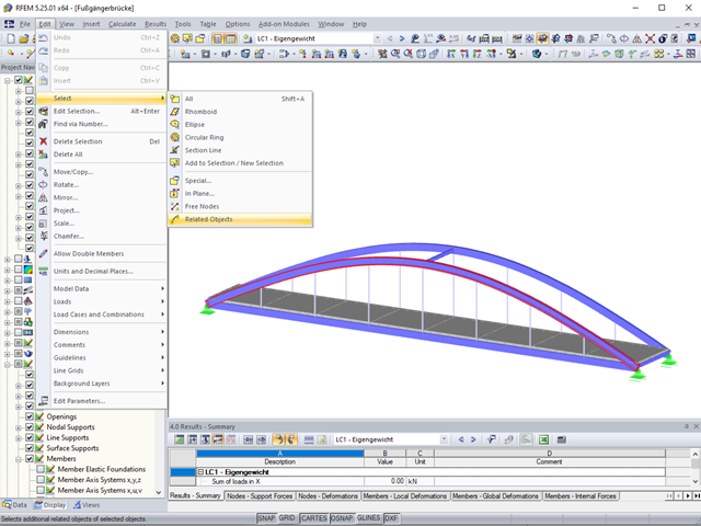
Sometimes it is necessary to add related objects, such as nodes and lines of a surface, to the selection in order to edit parts of the model.

If the geometry of a surface for which you must remove some of the existing boundary lines changes subsequently, you do not need to redefine the surface.

The same structures are often needed in several projects, such as the purlin with columns and braces in this example. The dimensions can be changed directly in RFEM or RSTAB by shifting the nodes.
In RFEM 5 and RSTAB 8, you can add visual objects to the model in order to make a convincing impression on your client when presenting the structural model. These objects allow both laypersons and engineers to better understand the dimensions of the system.

The classification of cross-sections according to EN 1993-1-1 using Table 5.2 is a simple method for designing the local buckling of cross-section parts. For cross-sections of cross-section class 4, it is then necessary to determine the effective cross-section properties according to EN 1993-1-5 in order to consider the influence of local buckling in the ultimate limit state designs.
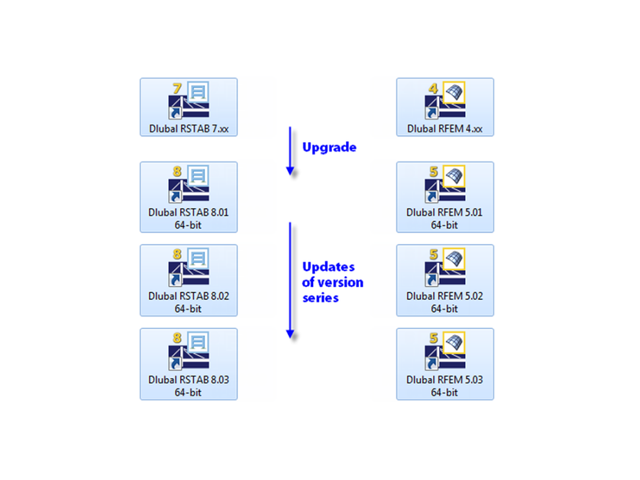
When updating within a version series (for example, RFEM 5.01.01 to 5.01.02), the old program files are removed and replaced by new ones. The project data, of course, remain unchanged. When updating to the next version series (for example, RFEM 5.02.01), the new version is installed in parallel. The program files are located in different directories, so the previous version is still available.
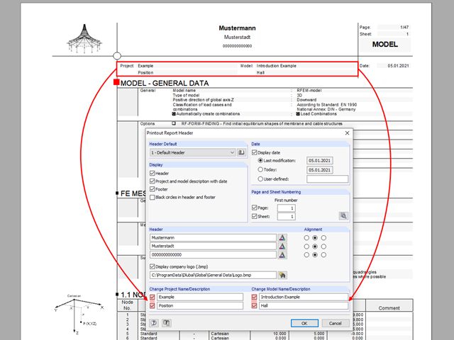
The name of the project/model from the General Data is shown in the header of the printout report by default. In RFEM 5 and RSTAB 8, the model name can be changed manually in the printout report independently of the actual name.